Machine Learning & Signals Learning
22 ARX
The ARX (Auto-Regressive with eXtra input or Auto-Regressive eXogenic) model extends the AR approach by incorporating an additional input signal \(x[n]\) that influences the output \(y[n]\). The term "exogenous" indicates that the additional input signal comes from outside the system, unlike an AR model that relies solely on past values of the output.
Systems classification Two class of models:
-
• Endogenic/endogenous system is a system without inputs.
-
• Exogenic/exogenous is a system with inputs.
The \(ARX(p,q)\) model is given by
\(\seteqnumber{0}{}{0}\)\begin{equation} \begin{aligned} y[n] &= h_1y[n-1] + \cdots + h_py[n-p] \\ &\quad + b_1x[n-1] + \cdots + b_qx[n-k] + \epsilon [n], \end {aligned} \end{equation}
where
-
• \(h_i\) are AR coefficients related to the past of \(y[n]\),
-
• \(b_i\) are he coefficients that relate the current output \(y[n]\) to past values of the exogenous input \(x[n]\)
-
• \(\epsilon [n]\) is noise or modeling error.
Adding an exogenous input changes what goes into the regressor matrix. Each section of this chapter adds one more ingredient to it: past values of the input, past noise terms, removal of a trend, several signals at once, or a non-linear mapping in place of the weighted sum. Table 22.1 lists the resulting models and the ingredients each one uses. The first two rows are the models of the previous chapter, repeated as the starting point.
| Model | past \(y[n-i]\) | past \(x[n-k]\) | noise \(\epsilon [n-k]\) | trend removal | vector | non-linear | Sec. |
| AR(\(p\)) | ✓ | 21.3 | |||||
| ARMA(\(p,q\)) | ✓ | ✓ | 21.7 | ||||
| ARX(\(p,q\)) | ✓ | ✓ | 22.4 | ||||
| ARMAX | ✓ | ✓ | ✓ | 22.6 | |||
| ARI(\(p,d\)) | ✓ | ✓ | 22.7 | ||||
| ARIMA(\(p,d,q\)) | ✓ | ✓ | ✓ | 22.7 | |||
| ARIMAX(\(p,d,q\)) | ✓ | ✓ | ✓ | ✓ | 22.7 | ||
| NARX | ✓ | ✓ | ✓ | ✓ | 22.8 | ||
| VAR(\(p\)) | ✓ | ✓ | 22.9 |
22.1 Cross-Correlation Function (CCF)
The goal is to predict \(y[n]\) from \(x[n-k]\) with a single exogenous term at lag \(k\) by \(b_k\) coefficient,
\(\seteqnumber{0}{}{1}\)\begin{equation} \hat {y}[n]=b_k x[n-k], \end{equation}
The resulting MSE-based loss function is of the form
\(\seteqnumber{0}{}{2}\)\begin{equation} \mathcal {L}(b) = \frac {1}{2}\sum _n \left (y[n] - b_kx[n-k])\right )^2 \end{equation}
with the solution by
\(\seteqnumber{0}{}{3}\)\begin{equation} \frac {d\mathcal {L}(b)}{db} =\sum _n (y[n]-b_kx[n-k])(-x[n-k])=0 \end{equation}
The corresponding solution is
\(\seteqnumber{0}{}{4}\)\begin{equation} \label {eq-ccf-bk} b_k = \frac {\sum _n y[n]x[n-k]}{\sum _n x^2[n-k]}. \end{equation}
Cross-Correlation Function The resulting coefficients are related to the cross-correlation function,
\(\seteqnumber{0}{}{5}\)\begin{equation} \label {eq-ccf} R_{\bx \by }[k]=\sum _n y[n]x[n-k],k=-L+1,\ldots ,L-1 \end{equation}
so that the numerator of Eq. (22.5) is \(R_\bxy [k]\) itself, and a peak at a positive lag \(k\) marks an input leading the output by \(k\) samples, which is the lag worth adding to the model.
Similar to the ACF, cross-correlation can also be defined in biased, unbiased, or normalized forms:
\(\seteqnumber{0}{}{6}\)\begin{align} R_{\bxy ,biased}[k] &= \frac {1}{L}R_\bxy [k]\\ R_{\bxy ,unbiased}[k] &= \frac {1}{L-\abs {k}}R_\bxy [k]\\ R_{\bxy ,norm}[k] &= \frac {R_\bxy [k]}{\sqrt {R_\bx [0]R_\by [0]}} \end{align} Note, these modification are available only if \(x[n]\) and \(y[n]\) are of the same length. Otherwise, only \(R_{\bx \by }[k]\) (22.6) is used.
The normalized cross-correlation function has correlation coefficient interpretation,
\(\seteqnumber{0}{}{9}\)\begin{equation} R_{\bxy ,norm}[k] \approx \rho _{\bxy }[k] \end{equation}
Properties:
\(\seteqnumber{0}{}{10}\)\begin{align} R_\bxy [k] &= R_\byx [-k]\\ R_\bxy [-k] &= R_\byx [k]\\ \abs {R_\bxy [k]} &\leqslant \sqrt {R_\bx [0]R_\by [0]}\\ \abs {R_\bxy [k]} &\leqslant \frac {1}{2}\left [R_\bx [0]+R_\by [0]\right ] \end{align}
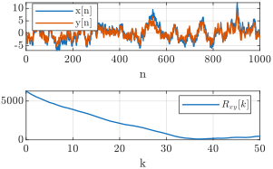
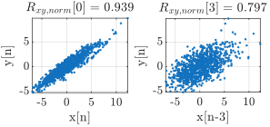
Interpretation If there is a strong correlation at some lag \(k\), it suggests that \(y[n]\) is influenced by \(x[n-k]\). In an ARX setting, identifying the lag \(k\) at which the cross-correlation peaks can guide the selection of \(q\) and help determine which past inputs are most relevant for predicting \(y[n]\).
-
Example 22.1: The solution in Eq. (20.23) is
\(\seteqnumber{0}{}{14}\)\begin{equation} \hat {A} = \frac {R_\bxy [0]}{R_\bx [0]} \end{equation}
Cross-Covariance Function For simplicity, a zero-average, \(\bar {x}[n]=\bar {y}[n]=0\), was assumed. When either of the signals is non-zero mean, the subtraction of signal average from the signal before cross-correlation calculation is termed as cross-covariance. It is similar to auto-correlation and auto-covariance functions in Sec. 21.1.4.
22.1.1 Time-Difference Estimation
A common special case is that the output is nothing but a scaled, delayed and noisy copy of the input,
\(\seteqnumber{0}{}{15}\)\begin{equation} \label {eq-ccf-delay-model} y[n] = A\,x[n-n_0] + \epsilon [n], \end{equation}
where the delay \(n_0\) is the unknown of interest.
This is the common model of a signal recorded by two sensors at different distances from the same source, of a transmitted pulse and its echo, or of a reference channel and a propagated one.
The lag search is the least-squares fit The section already solved the fit at a given lag: \(b_k\) (22.5) returns the best gain \(b_k\) for the single-term predictor \(\hat {y}[n]=b_kx[n-k]\). For \(\abs {k}\ll L\) its denominator is the input energy \(R_\bxx [0]\), so
\(\seteqnumber{0}{}{16}\)\begin{equation} b_k \approx \frac {R_\bxy [k]}{R_\bxx [0]}. \end{equation}
What remains is to choose \(k\). Substituting \(b_k\) back into the loss gives the residual it leaves (see also auto-correlation result in Eq. (21.33)),
\(\seteqnumber{0}{}{17}\)\begin{equation} \label {eq-ccf-min-loss} \loss _{min}(k) = \frac {1}{2}\left (R_\byy [0] - \frac {R^2_\bxy [k]}{R_\bxx [0]}\right ), \end{equation}
Neither \(R_\byy [0]\) nor \(R_\bxx [0]\) depends on \(k\), so minimizing the residual over the lag is the same as maximizing \(R^2_\bxy [k]\),
\(\seteqnumber{0}{}{18}\)\begin{equation} \label {eq-ccf-tdoa} \hat {n}_0 = \arg \max \limits _{k}\abs {R_\bxy [k]},\qquad \hat {A} = \frac {R_\bxy [\hat {n}_0]}{R_\bxx [0]},\qquad \hat {\tau } = \frac {\hat {n}_0}{f_s}. \end{equation}
The absolute value admits a polarity inversion, \(A<0\).
-
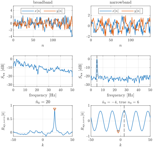
Example 22.2: A broadband \(x[n]\) of \(L=1000\) samples, sampled at \(f_s=100\) Hz, is delayed by \(n_0=20\) samples and scaled by \(A=0.8\) before independent noise is added, as in Eq. (22.16). Searching \(\abs {k}\le 50\) in the left column of Fig. 22.2 gives \(\hat {n}_0=20\) samples, a peak of \(R_{\bxy ,norm}[\hat {n}_0]=0.876\), and
\(\seteqnumber{0}{}{19}\)\begin{equation} \hat {A} = \frac {R_\bxy [20]}{R_\bxx [0]} = 0.814,\qquad \hat {\tau } = \frac {20}{100} = 0.2~\text {s}, \end{equation}
recovering both the delay and the gain.
-
Example 22.3: Repeat the estimate for a narrowband input,
\(\seteqnumber{0}{}{20}\)\begin{equation*} x[n]=\cos \left (2\pi f_0n/f_s\right )+0.5\epsilon _x[n],\qquad f_0=5~\text {Hz}, \end{equation*}
sampled at \(f_s=100\) Hz over \(L=1000\) samples and delayed by \(n_0=6\) samples as in Eq. (22.16). The right column of Fig. 22.2 shows the pair, the spectrum of the input, and the CCF.
-
Solution: The middle panel already decides the outcome. The input power sits in a single line at \(f_0\), standing \(22.4\) dB above the median level of the spectrum, against \(10.6\) dB for the broadband input of the previous example. Such a spectrum has an auto-correlation that oscillates at \(f_0\) without decaying, and the CCF of Eq. (22.16) is that auto-correlation shifted to \(k=n_0\).
The bottom panel is therefore not a peak but a train of lobes, alternating sign every \(f_s/2f_0=10\) lags and repeating every \(f_s/f_0=20\) lags. Their heights are
\(\seteqnumber{0}{}{20}\)\begin{equation} \begin{aligned} R_{\bxy ,norm}[6] &= \phantom {-}0.669, &\qquad R_{\bxy ,norm}[-4] &= -0.678,\\ R_{\bxy ,norm}[-14] &= \phantom {-}0.663, &\qquad R_{\bxy ,norm}[26] &= \phantom {-}0.638, \end {aligned} \end{equation}
four candidates within \(0.04\) of one another. The estimator of Eq. (22.19) takes the largest in magnitude and returns
\(\seteqnumber{0}{}{21}\)\begin{equation} \hat {n}_0 = -4, \end{equation}
missing the true delay by \(10\) samples, exactly half a carrier period. Nothing but noise separates the lobes, so another realization of the same experiment hands the win to a different one.
Knowing the polarity of the coupling helps only halfway. With \(A>0\) assumed, the search is restricted to the positive lobes and returns \(\hat {n}_0=6\) here, but those lobes are themselves \(20\) lags apart and equally tied. The ambiguity is reduced from half a carrier period to a full one, not removed.
-
Which normalization The biased and normalized forms of Eq. (22.6) rescale \(R_\bxy [k]\) by a constant, so they leave the location of the peak untouched and only change the number printed on the axis; the normalized form is the convenient one, since its peak height is directly the correlation coefficient of the fit. The unbiased form is the one to avoid: dividing by \(L-\abs {k}\) inflates the tail of the lag axis, where few terms are averaged, and manufactures spurious peaks far from the true delay. This is the same argument that favors the biased ACF in the peak search of Sec. 21.2.2.
Tip:
-
• Sub-sample refinement: a true delay is rarely an integer number of samples, whereas Eq. (22.19) searches a grid of spacing \(1/f_s\). Fitting a parabola through \(R_\bxy [\hat {n}_0-1]\), \(R_\bxy [\hat {n}_0]\) and \(R_\bxy [\hat {n}_0+1]\) and taking its vertex gives the fractional correction
\(\seteqnumber{0}{}{22}\)\begin{equation} \delta = \frac {1}{2}\cdot \frac {R_\bxy [\hat {n}_0-1]-R_\bxy [\hat {n}_0+1]}{R_\bxy [\hat {n}_0-1]-2R_\bxy [\hat {n}_0]+R_\bxy [\hat {n}_0+1]}, \end{equation}
so that \(\hat {\tau }=(\hat {n}_0+\delta )/f_s\). This is the lag-axis counterpart of the parabolic peak refinement of the periodogram in Eq. (20.48).
The sign of the lag is a convention
Which of the two signals is shifted in Eq. (22.6) is a choice, not a property of the data, and books and software packages do not agree on it. Reversing the choice mirrors the lag axis, \(R_\bxy [k]=R_\byx [-k]\), so the same pair of signals can show its peak at \(k=+6\) in one source and at \(k=-6\) in another.
The convention adopted here shifts the input, so that a peak at a positive lag means the input leads the output. For example, in MATLAB it is xcorr(y,x), the output passed first; xcorr(x,y) returns the mirrored axis.
Before reading a lag off any implementation, check the documentation or just cross-correlate a signal with a delayed copy of itself, and see which side the peak lands on.
22.2 Cross-Spectral Density (CSD)
22.2.1 Definition
The Cross-Spectral Density (CSD) is the frequency-domain counterpart to the cross-correlation function (CCF). Following the Wiener-Khinchin theorem discussed in Sec. 21.2, the CSD is defined as the Fourier transform of the cross-correlation sequence \(R_{\bx \by }[n]\):
\(\seteqnumber{0}{}{23}\)\begin{equation} S_{\bxy }[k] = \DFTtr {R_{\bxy }[n]} \end{equation}
For finite-time signals, using the Discrete Fourier Transform (DFT), it is practically estimated using the cross-periodogram:
\(\seteqnumber{0}{}{24}\)\begin{equation} S_{\bx \by }[k] = X^*[k] Y[k] \end{equation}
where \(X[k]\) and \(Y[k]\) are the DFTs of the signals \(x[n]\) and \(y[n]\), and \(X^*[k]\) denotes the complex conjugate of \(X[k]\).
-
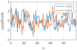
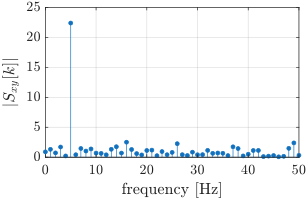
Example 22.4: Consider two short noisy sinusoids of frequency \(f_0=5\) Hz sampled at \(f_s=100\) Hz, where \(y[n]\) is a delayed copy of \(x[n]\) with delay \(n_0=6\) samples,
\(\seteqnumber{0}{}{25}\)\begin{align*} x[n] &= \cos (2\pi f_0 n/f_s) + 0.5\,\epsilon _x[n]\\ y[n] &= \cos (2\pi f_0 (n-n_0)/f_s) + 0.5\,\epsilon _y[n] \end{align*} with \(L=100\) samples. The signals are shown in Fig. 22.3(a). Because the records are short, the cross-periodogram is a noisy estimate of the true CSD; nevertheless, \(\abs {S_{\bxy }[k]}\) exhibits a clear peak at the sinusoid frequency, as seen in Fig. 22.3(b).
Properties
Unlike the PSD (\(S_{\bx \bx }[k]\)), which is strictly real and non-negative, the CSD is generally a complex-valued function.
-
• Magnitude: \(\abs {S_{\bx \by }[k]}\) indicates the strength of the shared power between the two signals at frequency bin \(k\).
-
• Phase: \(\angle S_{\bx \by }[k]\) represents the phase difference between \(y[n]\) and \(x[n]\) at that specific frequency. For the pure delay of Eq. (22.16) this phase is linear in \(k\), \(\angle S_{\bxy }[k] = -2\pi k n_0/L\), so the delay estimated in Sec. 22.1.1 from the CCF peak can equivalently be read off the slope of the phase.
-
• Conjugate Symmetry: \(S_{\bx \by }[k] = S_{\by \bx }^*[k]\).
While the CCF shows the linear relationship across time lags, the CSD reveals how that relationship is distributed across different frequencies.
22.2.2 Cross-Coherence
The cross-coherence (or magnitude-squared coherence) is the frequency-domain counterpart of the normalized CCF: it expresses, at each frequency bin \(k\), how strongly the two signals share a stable linear relation.
Built directly from the CSD \(S_{\bxy }[k]\) and the two PSDs \(S_{\bxx }[k]\), \(S_{\byy }[k]\), it is defined by
\(\seteqnumber{0}{}{25}\)\begin{equation} \gamma _{\bxy }^2[k] = \frac {\abs {S_{\bx \by }[k]}^2}{S_{\bx \bx }[k]\,S_{\by \by }[k]} \end{equation}
which can be read as the squared correlation coefficient at frequency \(k\), mirroring the time-domain identity \(R_{\bxy ,norm}^2[k]\approx \rho _{\bxy }^2[k]\) 1.
The cross-coherence is bounded between 0 and 1 for all frequency bins:
\(\seteqnumber{0}{}{26}\)\begin{equation} 0 \leqslant \gamma _{\bxy }^2[k] \leqslant 1 \end{equation}
1 The discussion on the complex-valued \(\gamma _{\bxy }[k] = \frac {S_{\bx \by }[k]}{\sqrt {S_{\bx \bx }[k]\,S_{\by \by }[k]}}\) is beyond the scope of this chapter.
Interpretation
-
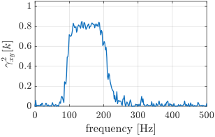
• A value near 1 means that, across realizations, the two signals oscillate at frequency \(k\) with a consistent gain and phase offset (a stable linear coupling).
-
• A value near \(0\) means no consistent coupling at that frequency: gain or phase varies from segment to segment.
A typical estimate is shown in Fig. 22.4, where \(y[n]\) is a band-limited filtered version of \(x[n]\) corrupted by independent noise.
The requirement for averaging
For a single periodogram, \(S_{\bx \by }[k]=X^*[k]Y[k]\), \(S_{\bx \bx }[k]=\abs {X[k]}^2\), \(S_{\by \by }[k]=\abs {Y[k]}^2\), so
\(\seteqnumber{0}{}{27}\)\begin{equation} \gamma _{\bx \by }^2[k] = \frac {\abs {X^*[k]Y[k]}^2}{\abs {X[k]}^2\abs {Y[k]}^2} = 1 \end{equation}
identically, regardless of the underlying signals. Coherence becomes meaningful only after averaging \(M>1\) segments (Welch / Bartlett, Sec. 20.7.4).
22.3 ARX(0,q) model
The ARX(0,q) model describes a scenario where the output \(y[n]\) depends purely on the past values of an external (exogenous) input \(x[n]\), without feedback from its own past outputs [12, Example 4.3, pp. 90]
\(\seteqnumber{0}{}{28}\)\begin{equation} \begin{aligned} y[n] &= b_1x[n-1] + \cdots + b_{q}x[n-q] + \epsilon [n]\\ &= \sum _{k=1}^q b_kx[n-k] + \epsilon [n] \end {aligned} \end{equation}
In matrix form, the past values are arranged into a matrix \(\bX \),
\(\seteqnumber{0}{}{29}\)\begin{equation} \underbrace {\begin{bmatrix} \hat {y}[1] \\ \hat {y}[2]\\ \vdots \\ \hat {y}[L-1] \end {bmatrix}}_{\hat {\by }} = \underbrace {\left [\begin{bmatrix} x[0] & 0 & \cdots & 0 \\ x[1] & x[0] & \cdots & 0 \\ \vdots & \vdots & \ddots & \vdots \\ x[L-2] & x[L-3] & \vdots & x[L-m-2] \end {bmatrix}\right ]}_{\bX } \underbrace {\begin{bmatrix} b_1 \\ \vdots \\ b_{q} \end {bmatrix}}_{\bb } \end{equation}
with \(\hat {\by }\in \Re ^{L-1},\bX \in \Re ^{(L-1)\times q},\bb \in \Re ^{q}\). The resulting \(\bb \) coefficients are found by the corresponding LS minimization. Similar ot AR model, the solution is also comprised of the corresponding auto-correlations \(R_{\bx \bx }[k]\) resulted for \(\bX ^T\bX \) and cross-correlations \(R_{\bx \by }[k]\) resulted from \(\bX ^T\by \). This reveals that the solution leverages both the structure of the input’s autocorrelation and the input-output cross-correlation.
Interpretation The model is essentially a linear filter of \(x[n]\).
22.4 General ARX model
In a general ARX(p,q) model, the output is represented as a linear combination of both its own past values and the past values of an exogenous input. LS formulation involves matrix \(\bX \) that is constructed from past values of \(x[n]\) and \(y[n]\), shifted according to the lags involved. The vector \(\bw \) includes both \(h_i\) and \(b_k\) values.
-
Example 22.5: ARX(3,3) model with signals
\(\seteqnumber{0}{}{30}\)\begin{align*} x[n] &= x[0],x[1],\ldots ,x[7]\\ y[n] &= y[0],y[1],\ldots ,y[7] \end{align*} The required difference equation is
\(\seteqnumber{0}{}{30}\)\begin{equation} \begin{aligned} \hat {y}[n] &= h_1y[n-1] + h_2y[n-2] + h_3y[n-2] \\ &\quad + b_1x[n-1] + b_2x[n-2] + b_3x[n-3] \end {aligned} \end{equation}
Find prediction of \(\hat {y}[8]\).
-
Solution: The coefficients are given by
\(\seteqnumber{0}{}{31}\)\begin{equation} \arg \min \limits _{\bw }\norm {\by -\bX \bw } \end{equation}
where
\(\seteqnumber{0}{}{32}\)\begin{align} \bX = \begin{bmatrix} x[0] & 0 & 0 & y[0] & 0 & 0 \\ x[1] & x[0] & 0 & y[1] & y[0] & 0 \\ x[2] & x[1] & x[0] & y[2] & y[1] & y[0] \\ x[3] & x[2] & x[1] & y[3] & y[2] & y[1] \\ x[4] & x[3] & x[2] & y[4] & y[3] & y[2] \\ x[5] & x[4] & x[3] & y[5] & y[4] & y[3] \\ x[6] & x[5] & x[4] & y[6] & y[5] & y[4] \end {bmatrix}, \\ \bw = \begin{bmatrix} b_1 \\ b_2 \\ b_3 \\ h_1 \\ h_2 \\ h_3 \end {bmatrix}, \by = \begin{bmatrix} y[1] \\ y[2] \\ y[3]\\ y[4]\\ y[5] \\y[6] \\ y[7] \end {bmatrix}\nonumber \end{align} The prediction of \(\hat {y}[8]\) is straightforward after finding the prediction coefficients by LS minimization. The resulting calculation is comprised of the corresponding \(R_{\bx \bx }[k]\) and \(R_{\bx \by }[k]\) values.
-
22.5 Time-Domain Filtering
-
Goal: Use AR model for signal enhancement. In this problem there two common versions that include signal and noise combinations that differs by signal availability during the training. We assume both signal and noise are stationary. In he first one, clean and another noisy versions are available,
\(\seteqnumber{0}{}{33}\)\begin{equation} \begin{cases} x[n]\\ y[n]=x[n] + \epsilon [n] \end {cases} \end{equation}
In another one (Wiener filter), noise and noisy versions are available,
\(\seteqnumber{0}{}{34}\)\begin{equation} \begin{cases} \varepsilon [n]\\ y[n]=x[n] + \epsilon [n] \end {cases} \end{equation}
In either case, the learned AR(p) model can be used.
Noise filtering (denoising)
We have training data \(\left \lbrace x[n], y[n]\right \rbrace _{n=0}^{L-1}\) and we are interested to learn coefficients \(h_k\), such that
\(\seteqnumber{0}{}{35}\)\begin{equation} \hat {x}[n] = \sum _{k=0}^{p}h_k y[n-k] \end{equation}
The key idea is to construct the AR matrix \(\bX \) (as in (21.43)) from the shifted versions of \(y[n]\) rather than \(x[n]\). By fitting an AR model the resulting coefficients effectively learn how to reconstruct the clean signal from the noisy input. The matrices are
\(\seteqnumber{0}{}{36}\)\begin{equation} \begin{aligned} \bX &= \begin{bmatrix} y[p] & y[p-1] & \cdots & y[0]\\ y[p+1] & y[p] & \ldots & y[1]\\ \vdots & \cdots & \ddots & \vdots \\ y[L-1] & y[L-2] & \cdots & y[L-1-p] \end {bmatrix},\\ \by &= \begin{bmatrix} x[p] \\ x[p+1] \\ \vdots \\ x[L-1] \end {bmatrix} \end {aligned} \end{equation}
and the resulting coefficients can be found by the normal equation.
Using notation in Sec. 21.3.1, the problem can be rewritten as matrix \(\bR \) of \(R_\byy [k]\) elements and vector \(\br \) with \(R_\bxy [k]\) elements. The resulting \(h_k\) values are optimal in the sense of MSE.
This approach sets the foundation for adaptive filtering methods, where the model continuously adjusts its parameters to best estimate the clean signal under changing noise conditions.
22.6 ARMAX
The model that combines ARMA (signal history and noise) together with exogenous input (ARX model),
\(\seteqnumber{0}{}{37}\)\begin{equation} \begin{aligned} y[n] &= h_1y[n-1] + \cdots + h_{n_a}y[n-n_a] \\ &+ b_1x[n-1] + \cdots + b_{n_b}x[n-n_b]\\ &+ c_1\epsilon [n-1] + \cdots + c_{n_c}\epsilon [n-n_c]+ \epsilon [n] \end {aligned} \end{equation}
22.7 ARI, ARIMA, ARIMAX
When time series data exhibit trends, the basic AR, MA, and ARMA models may not be directly suitable. Trends refer to a systematic change in the mean level of the series, often increasing or decreasing over time. To accommodate such trends, de-trending can be applied before fitting ARMA-type models.
22.7.1 De-trending/Differencing
The basic model with linear trend is
\(\seteqnumber{0}{}{38}\)\begin{equation} y[n] = A + Bn + \epsilon [n], \end{equation}
where \(B\) is the slope of the trend. Let’s define
\(\seteqnumber{0}{}{39}\)\begin{equation} \begin{aligned} y[n] - y[n-1] &= A + Bn + \epsilon [n] - A - B(n-1) - \epsilon [n-1]\\ &= B + \epsilon [n] - \epsilon [n-1] \end {aligned} \end{equation}
This is known as first-order differencing that effectively removes the constant slope.
The quadratic (or parabolic) trend is given by
\(\seteqnumber{0}{}{40}\)\begin{equation} y[n] = an^2 + bn + c \end{equation}
Applying the differencing twice,
\(\seteqnumber{0}{}{41}\)\begin{align*} y'[n] &= y[n] - y[n-1]\\ y''[n] &= y'[n] - y'[n-1]\\ &= y[n] - y[n-1] - (y[n-1] - y[n-2]) \\ &= y[n] - 2y[n-1] + y[n-2] \end{align*} can remove a quadratic trend.
In practice, differencing is often done as a preliminary step. If a single differencing is needed to achieve stationarity, this is referred to as \(d=1\); if twice, \(d=2\), and so forth.
22.7.2 ARI Family
ARI(p,d) If an AR model (p) is applied to data that have been differenced \(d\) times to remove trend. The “I” stands for “Integrated”, indicating differencing to remove trend.
ARIMA(p,d,q) ARMA model with de-trending is termed ARIMA(p,d,q). ARIMA(p,0,q) is actually ARMA(p,q).
ARIMAX(p,d,q) Similar to ARMAX, ARIMAX includes exogenous inputs (X) along with the ARIMA model.
22.8 Non-linear AR and ARX Models
A non-linear autoregressive model replaces the linear combination \(h_{1}y[n-1]+\cdots +h_{p}y[n-p]\) with a non-linear mapping implemented by a non-linear model approximation, e.g. by neural network:
\(\seteqnumber{0}{}{41}\)\begin{equation} \hat {y}[n]= f(y[n-1],\ldots , y[n-p]) + \epsilon [n] \end{equation}
where \(f(\cdot ;\bw )\) is the model and \(\bw \) its weights.
For neural network with purely linear activations the NAR(\(p\)) collapses to the classical AR(\(p\)).
The corresponding NARX model is
\(\seteqnumber{0}{}{42}\)\begin{equation} \label {eq-narx} \hat {y}[n] \;=\; f(\bx ,\by ) + \epsilon [n] \end{equation}
The network learns an arbitrary non-linear mapping from the selected lags of \(y[n]\) and \(x[n]\) to the current output.
22.9 Vector AR (VAR)
The goal is to use AR multivariate prediction of an \(N\)-dimensional signal \(\by [n]\) by its \(L\) historic values,
\(\seteqnumber{0}{}{43}\)\begin{equation} \begin{Bmatrix} \begin{bmatrix} y_0[0]\\[3pt] y_1[0]\\[3pt] \vdots \\ y_{N-1}[0] \end {bmatrix}, \begin{bmatrix} y_0[1]\\[3pt] y_1[1]\\[3pt] \vdots \\ y_{N-1}[1] \end {bmatrix} \begin{matrix} \cdots \\[3pt] \cdots \\[3pt] \cdots \\[5pt] \cdots \end {matrix} \begin{bmatrix} y_0[L-1]\\[3pt] y_1[L-1]\\[3pt] \vdots \\ y_{N-1}[L-1] \end {bmatrix} \end {Bmatrix} \end{equation}
VAR(1) Model
For example, the VAR(1) model of 2-dimensional signal \((N=2)\) is
\(\seteqnumber{0}{}{44}\)\begin{equation} \begin{aligned} \begin{bmatrix} \hat {y}_0[n] \\[5pt] \hat {y}_1[n] \end {bmatrix} =\begin{bmatrix} a_{00} & a_{01}\\[5pt] a_{10} & a_{11}\\ \end {bmatrix} \begin{bmatrix} y_0[n-1]\\[5pt] y_1[n-1]\\ \end {bmatrix} + \begin{bmatrix} \epsilon _0[n]\\[5pt] \epsilon _1[n]\\ \end {bmatrix} \end {aligned} \end{equation}
In compressed matrix notation,
\(\seteqnumber{0}{}{45}\)\begin{equation} \hat {\by }[n] = \bA \by [n-1] + \bm {\epsilon }[n] \end{equation}
where \(\bA \in \real ^{N\times N},\bm {\epsilon }[n]\in \real ^N\).
History The relation to MA model is similar to univariate case,
\(\seteqnumber{0}{}{46}\)\begin{equation} \begin{aligned} \hat {\by }[n] &= \bA \by [n-1] + \bm {\epsilon }[n]\\ &= \bA (\bA \by [n-2] + \bm {\epsilon }[n-1]) + \bm {\epsilon }[n]\\ &= \bA ^2\by [n-2] + \bA \bm {\epsilon }[n-1] + \bm {\epsilon }[n]\\ &= \bA ^3\by [n-3] + \bA ^2\bm {\epsilon }[n-2] + \bA \bm {\epsilon }[n-1]+ \bm {\epsilon }[n]\\ \end {aligned} \end{equation}
The stability criterion is \(\abs {\lambda _{max}(\bA )}<1\).
\(\seteqnumber{0}{}{47}\)\begin{equation} \hat {\by }[n] = \bm {\mu } + \bA \by [n-1] + \bm {\epsilon }[n] \end{equation}
biases \(\bm {\mu } = \begin {bmatrix}\mu _0 \\ \mu _1\end {bmatrix}\).
VAP(p) Model
The further extension to \(p\) values history is straightforward,
\(\seteqnumber{0}{}{48}\)\begin{equation} \hat {\by }[n] = \bA _1\by [n-1] + \bA _2\by [n-2] + \ldots + \bA _p\by [n-p] \bm {\epsilon }[n] \end{equation}
Again, biased version is possible.
Coefficients
LS solution is straightforward by the organization of \(\by [n]\) values into the corresponding LS problem matrices.
Diagonal \(\bA \) matrix If matrix \(\bA \) is diagonal, the model reduces to a set of univariate independent models.
Trending The standard VAR models does not supply de-trending capabilities similar to the univariate ARI model. If de-trending is required, it is a part of signal pre-processing pipeline.
Non-linear extension The vector and non-linear extensions are not mutually exclusive. A NARX model (Sec. 22.8) whose output layer has \(N\) units maps the selected lags to the whole \(N\)-dimensional output at once,
\(\seteqnumber{0}{}{49}\)\begin{equation} \hat {\by }[n] = f\left (\by [n-1],\ldots ,\by [n-p],\bx [n-1],\ldots ,\bx [n-q]\right ) + \bm {\epsilon }[n], \end{equation}
and reduces to VAR(\(p\)) when \(f(\cdot )\) is linear, exactly as NAR(\(p\)) reduces to AR(\(p\)).